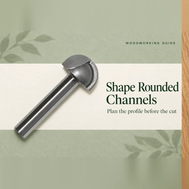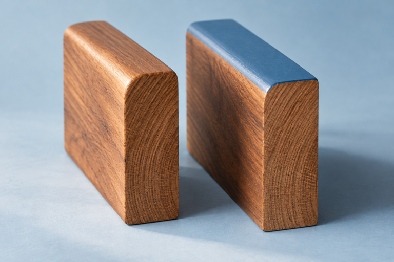
The QG square-tooth cutter set uses two complementary cutting profiles: cutter I removes the middle of an edge to form a groove, while cutter II removes material above and below a central tongue. The tongue is the wood left between those cuts. Reading the pair this way makes the JEEFOO catalogue drawing easier to understand and explains why the two tools have different silhouettes.
The JEEFOO QG square-tooth cutter set is shown with tools marked I and II and a corresponding pair of square-sided joint sections. This article follows that specific drawing. It explains the visible geometry, rather than prescribing a machine setup.
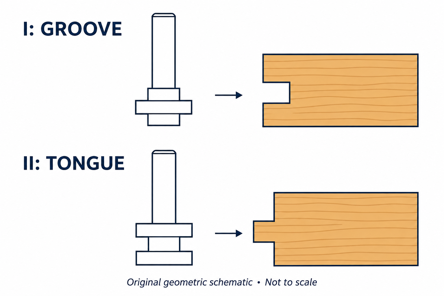
Cutter I puts its projecting cutting tier in the groove zone
In the QG drawing, cutter I has a central tier that projects farther outward than the body immediately above and below it. During the intended edge-forming operation, that projecting cutting region removes wood from the middle band of the edge. Material remains on either side of the resulting groove.
The central projection on the tool therefore corresponds to an opening in the wood. It does not stamp a wooden projection onto the component. A useful way to read the catalogue is to follow the region occupied by the working cutting profile, then identify which part of the original edge remains outside that region.
Cutter II removes the shoulders and leaves the tongue
Cutter II reverses that arrangement. Its visible profile has wider upper and lower cutting tiers, with a narrower region between them. The upper and lower tiers remove the two shoulder regions of the workpiece edge. The central strip of wood remains as the tongue.
That is why the recess between the tool’s outer tiers corresponds to a projection on the finished wood. The tool creates the tongue by cutting around it. The two cutting levels belong to the same illustrated tool profile, so they address the two sides of the tongue together geometrically. This does not establish that the full profile should be machined in one pass; stock removal and pass planning still depend on the approved tool and machine instructions.
How the QG square-tooth cutter set divides the work
Placed side by side, the QG cutters can initially look like variations of one shape. Their roles become clearer when the original wood edge is considered. Cutter I clears the central band. Cutter II clears the bands above and below it. The remaining wood sections are complementary because the removed regions are different.
Using the groove-forming profile on both mating edges would produce two grooves, not the groove-and-tongue pair shown in the QG catalogue. Likewise, treating cutter II as a second groove cutter misses the purpose of its two separated cutting tiers. The I and II labels identify distinct jobs within the set.
Separate roles also appear in CMT’s panel-door construction guide, which assigns the stick and cope profiles to different tools in its own rail-and-stile system. That is an independent example of paired joinery tooling, not a QG specification. CMT’s decorated profiles, dimensions and operating method should not be transferred to this square-tooth set.
Keep the illustration within its purpose
The QG reference supports a clear explanation of where each profile removes and retains wood. It does not show a bearing-guided assembly, a hidden rear cutting edge or a complete installed machine. The original illustration above deliberately omits those details.
For an actual job, the current QG drawing and supplier instructions must establish the working dimensions, permitted operation and machine compatibility. OSHA’s router guidance also emphasizes guarding, secure tool fastening and using tools only as intended. A simplified profile explanation cannot replace those requirements.
The central idea is visible in the QG square-tooth cutter set itself: one cutter removes the wood that becomes the groove; the other removes the wood around the tongue. Following those two removal patterns explains the set more precisely than treating its cutters as interchangeable shapes.