A freestanding oak wayfinding panel has a shallow relief on each face. On the drawing, a raised leaf on the front and a stem on the reverse are supposed to begin the same distance from one finished edge. At the inspection bench the two distances are different. Before moving either motif in CAM, establish whether both readings start at the same physical edge. Turning a panel so the reverse faces the reader can move that edge from the left of the drawing to the right of the inspector.
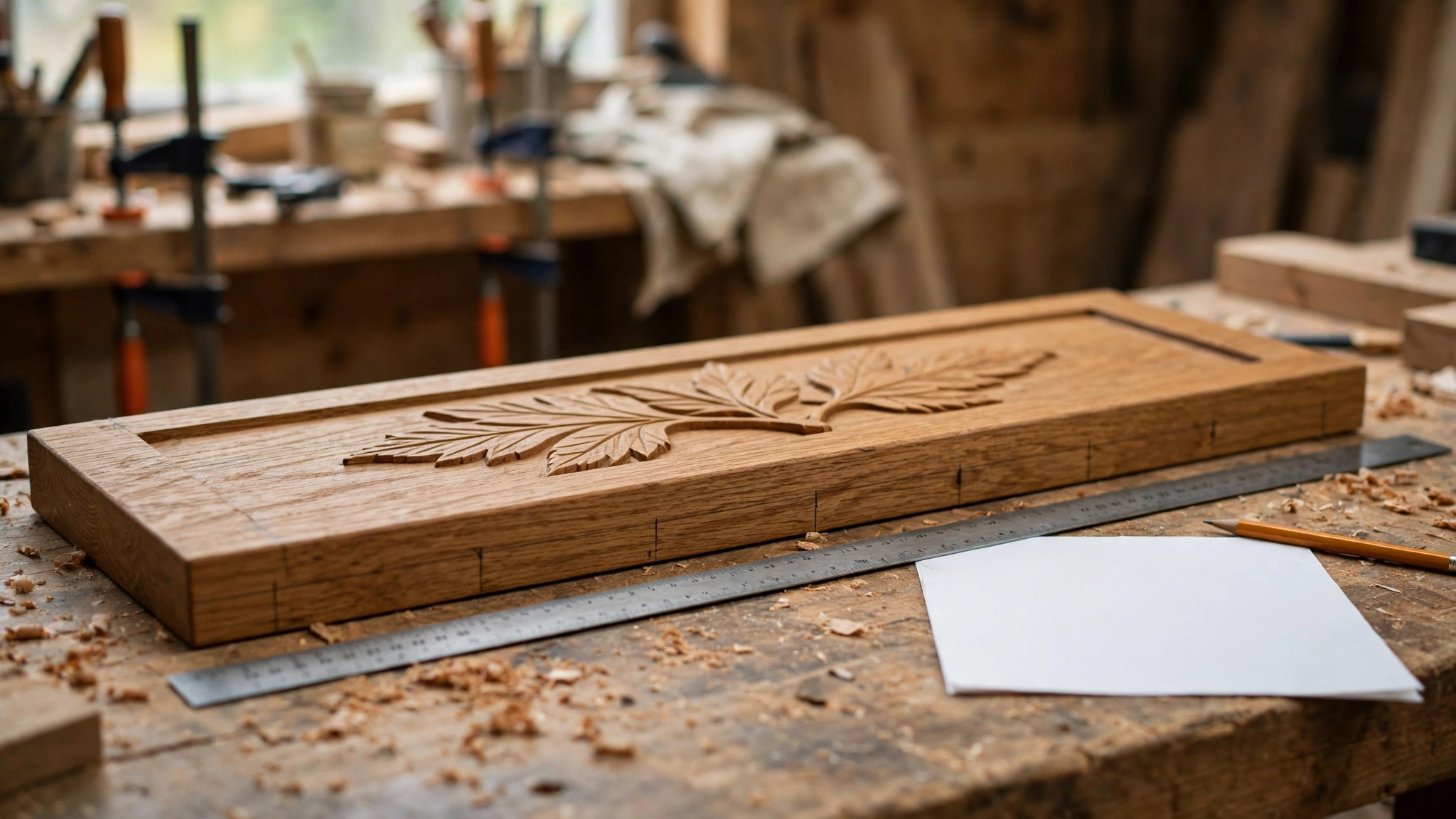
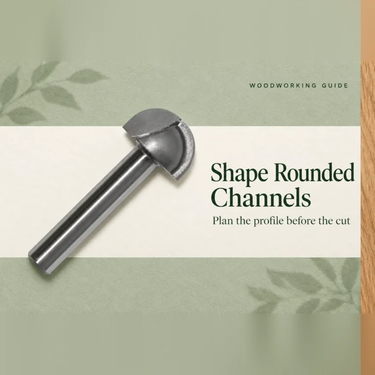
JEEFOO lists the GC as a tapered ball-nose tool for carving wood relief. In this example it forms the rounded contours on both faces. The registration and inspection procedure belongs to the panel design and its workholding plan. Cutter geometry alone does not establish where the second face will land relative to the first.
Mark an edge that survives the turn
On a trial blank, choose the finished edge from which the relationship is specified. Give it a name that appears on the drawing, the setup sheet and the inspection record. Put a matching mark on the waste margin or another approved area that survives both setups. Use a second mark to distinguish the end that stays uppermost in the installed panel. With only one edge mark, a person can still read a face upside down and select the wrong end of a long feature.
A sketch with both face views is worth keeping at the bench. Draw the two marks in their physical positions for each view. Ask the person reading the reverse drawing to point to the matching edge on the blank before taking a measurement. If the sketch and the physical marks disagree, resolve which face view was supplied before evaluating the toolpath.
Use a landmark that can be found on the cut
The outside of a rounded leaf can look wider or narrower as the light moves. If the design permits, agree on a particular feature that the inspector can locate without tracing a shadow. A specified section through a leaf and a defined point on that section are easier to revisit than a hand-drawn outline along the whole leaf. Record the method with the feature locations. If the design requires a coordinate from the digital model and the physical inspection cannot reproduce it reliably, obtain a suitable measurement method before signing off the trial.
Record each face reading from the marked datum with the panel held in an approved inspection position. If an earlier record uses a different edge, preserve that value and label its origin. Recheck from the common datum before deciding whether the offset is real.
Distinguish a changed origin from a shifted cut
When both landmarks agree with the design after the common-edge check, update the inspection sheet with the two face views. When they still disagree, compare the blank marks and the setup records for each face. If several reverse features move together in the same direction, check the second setup’s position and the origin in the released file. If only the leaf or stem differs, review the feature definition and the corresponding local geometry before changing the entire face. Keep the first piece with its edge marks until someone can reproduce the result from the revised drawing and inspection sheet.
Related reading: Tapered Ball-Nose Router Bits for 3D Wood Relief: Check Surface Finish Before Sanding and CNC Router Bit Testing: Build a Repeatable First-Piece Check.